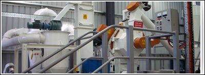
biomass gasification fuel production line
Recently, biomass gasification fuel is a hot topic and has been becoming a major energy source, prior to the fossil fuels like coal and petrol. Although fossil fuels is presently diminished in developed country, it is still widely used in rural communities of developing countries as their energy needs for cooking and heating. Biomass gasification fuel as a renewable energy is popular with more and more people. The raw material is all kinds of agricultural residues such as corn stalk, wheat stalk and etc. as well as the residues of forest industry are all available for the biomass gasification fuel production, except for rice husk and rice straw due to their higher ash content which is around 25%.
The production line is consisted by five parts: the construction part, the gasification unit, the gas tank or gas container, the pipeline and the indoor facilities or IC engine.
1) Construction part
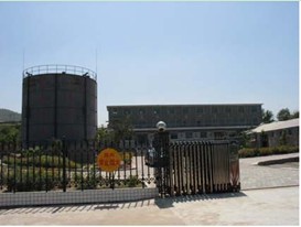
Biomass gasification station need a yard for the plant which is 50m×50m with enclosing wall around the yard. In the yard we need to construct a house which size is 17m in length, 8m in wide and 4.5m in high to install gasification unit and install a gas tank that should be 25m away from either the residential houses or put more open place. Also we need a storehouse which is fixed for depositing biomass fuel. In the case of power generation, an additional house is needed for the IC engine; the size depends on the requirement of the IC engine.
2) Gasification unit
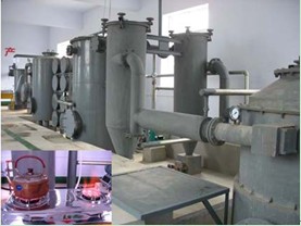
The gasification units includes a screw conveyer, a gasifier, two cyclones, a scrubber, a water separator, a biomass filter, a roots blower, a water seal, a control panel, two pumps and the necessary pipelines as well as the valves.
Biomass Gasifier
The gasifier is a downdraft fixed bed gasifier, it enables a high temperature in the reaction zone, the grate locates on bottom and adopts an enhanced air distributing system in order to ensure a complete reaction. Therefore it can widely suit to various types of biomass fuel including residues from lumber mill, branch of trees and agricultural refuses. The residue of gasification is mainly plant ash which can be used as fertilizer for the farm field.
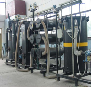
Cyclone separator
The separator is improved on the basis of the tangency-flow cyclone separator, and built up inside a stuffing layer in it for improving of the efficiency of dust removing. So the separator is named a stuffed cyclone separator. In the operating process, those impurities being removed by the stuff and dusts drop down to the dust cabin, and then take them out regularly, meanwhile the stuffing layer could be cleaned or replaced as well. In the gas conditioning system, two of separators in parallel connection are installed.
Scrubber
The scrubber catches and gathers the dust and tar content with water atomizing way in the directions of obverse or reverse according to different condition. The scrubbing water which amounts around 400kg according to the capacity of the system and circulates in the scrubber before it becomes dirty enough and is drained out. In general, it should be changed once a week. The scrubber is also designed as the heat exchanger, which can be cooled with the water in a water tank. The used scrubbing water is discharged into a pond of 20 m3 in volume for condensing, and then the condensed water in which the most parts are tar and ash content will be mixed with coal or other material for combustion. This will not pollute the environment.
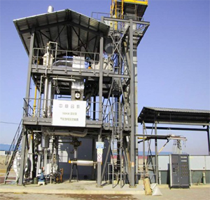
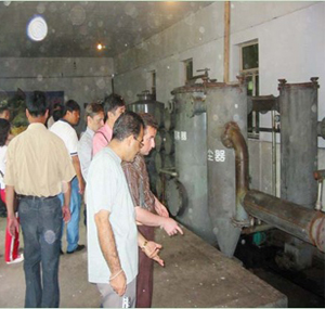
Biomass filter
This filter consists of single filtering layer in horizontal position using sawdust and chopping pieces in different size, which can also be taken out to be the feedstock of gasifier after drying in the open air.
Roots blower
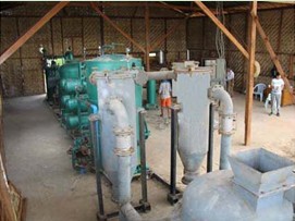
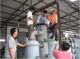
3) Gas tank or gas container
There are two gas tanks to be chosed, one is wet gas tank, as see in Fig 2, in cold area where there is the freezing problem, the general solution to prevent freezing is to put the water container underground and construct a greenhouse outside, and put inside the water some salt to lower the freezing temperature, the other is dry gas tank in which there is the flexible rubber membrane, as see in Fig 3, the rubber membrane works like a bellows, this kind of gas tank eliminates the problem of freezing and will save a lot of cost for maintenance, the cost for dry gas tank is similar to that of a wet gas tank with anti-freezing accessories. Of course, without considering of freezing problem, wet gas tank is economic and will cost only half of the one which contains anti-freezing accessories. In any case, the pressure of the gas tank is around 400 mm HO column.
In case for power generation, the volume of the gas tank is 200Nm3, which is used for stabilizing the producer gas composition and enable the IC engine to operate steadily, the pressure of the gas tank will depend on the requirement of IC engine.
Fig 2 Wet gas tank
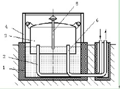
1water container 2 inlet 3 floating cover 4 guide track 5 overflow pipe 6 outlet
Fig 3 Dry gas tank

1 External cylinder 2 Flexible rubber membrane 3 floating cylinder block 4 piston 5 roof 6 balancing
4) PipelinesThe pipeline is underground installation, the depth of the pipe installation depends on the earth freezing layer thickness. Along the pipe, there is a gradient of 0.005, depending on the length of the pipe and the topography, there are certain amount of water container to collect the condensed water in the gas. The material of the pipe is polyethylene and the life span of the pipe is 50 years.
5) Indoor facilities
The indoor facilities consist of a cooking stove with biomass gasification producer gas as fuel, a gas meter, two valves, several meters of iron pipe and at most, one meter of flexible plastic tube. The power of the cooking stove is 3kW at an efficiency of around 50%; the capacity of the gas meter is 6Nm3/h. The gas pressure before the cooking stove is around 100mm H2O column.
6) IC engine
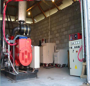
IC engine will be selected by user.


